
Direct answer
Choose direct measurement when the process can meet the optical path; choose extractive measurement when the sample must be controlled first.
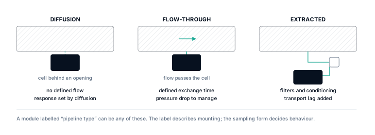
Direct in-pipe measurement removes the remote sample line but exposes the optical window to the real pressure, flow, moisture and contamination. Extractive measurement moves gas to a controlled cell, allowing filtration, flow control or drying, but adds transport delay, wetted surfaces, dead volume and possible composition change.
The defensible choice is the structure whose complete gas path preserves a representative sample within the required response time and maintenance boundary.
1. Draw the boundary from process gas to reported value
A sensor specification begins after gas reaches the optical path. A system decision begins at the process take-off. Between those points may be a fitting, probe, tubing, filter, liquid trap, pressure regulator, pump, flow restrictor, heated line and exhaust route. Each element can add time, volume, surface interaction or a new pressure and temperature condition.
In direct measurement, the boundary is shorter: process gas moves across an optical window located in or immediately at the pipeline. This can remove sample transport as a common source of error, a benefit discussed in a NIST TDLAS paper. It does not remove location error. A stagnant pocket, stratified flow, liquid film or poorly chosen insertion depth can still make the optical path unrepresentative.
2. Estimate sample transport before discussing T90
For a first ideal estimate, sample-line volume is divided by volumetric flow. For a round tube with internal diameter d and length L, the internal volume is:
tideal = V / Q Use the flow at the line’s actual pressure and temperature, or convert to a common reference basis.
Consider 10 m of tubing with a 4 mm internal diameter. Its geometric volume is approximately 0.126 L. At 1 L/min, one ideal line-volume time is about 7.5 s. That is not the complete T90: fittings, filters, regulators, mixing, diffusion, analyser-cell exchange and algorithm filtering add response. Dead legs can produce a long tail even when the main line volume looks small.
| Component | Controlled by | How to verify |
|---|---|---|
| Transport to analyser | Line volume, actual flow, pressure, fittings and mixing | Step change at the process take-off |
| Conditioning response | Filter, dryer, regulator, trap and heated surfaces | Test with the assembled conditioning path |
| Cell exchange | Cell volume and internal flow distribution | Step response at the module inlet |
| Optical / algorithm response | Scan, averaging and diagnostic logic | Defined signal-injection or rapid gas-step method |
US EPA Method 320 treats response as a system property by checking the complete measurement system. That is the correct principle when an analyser’s published module T90 is much shorter than the field sample path.
3. Ask whether the sample arriving is still the sample taken
Transport delay is visible; composition change can be harder to detect. Water may condense when a line cools below its dew point. A soluble or reactive gas can partition into that condensate. NH₃ can adsorb on unsuitable surfaces. A filter can capture aerosols that carry part of the target material. A dryer can intentionally or unintentionally change the basis of the reported concentration.
The project should state whether results are wet basis or dry basis and where pressure and temperature are defined. If the instrument reports mole fraction after removing water, it may not equal wet process mole fraction without a conversion. For gas paths with difficult species, a recovery test using the complete wetted path is more informative than a cell-only calibration.
4. Compare the structures with the same process question
| Decision | Direct in-pipe | Extractive |
|---|---|---|
| Measurement pressure | Process pressure at the optical window | Pressure after take-off, restriction, pump or regulator |
| Transport delay | No remote line; local gas exchange still matters | Line volume, flow and conditioning add delay |
| Contamination | Optics see process dust, liquid and deposits directly | Path can protect the cell, but components require maintenance |
| Sample change | Little intentional conditioning | Adsorption, condensation, leakage or wet/dry-basis changes possible |
| Maintenance | Requires safe access to the process fitting | Analyser can be accessible; long lines remain in service |
| Best reason to choose | Representative process measurement with minimal transport | Process gas needs controlled delivery before optical measurement |
5. Common failure modes and counterexamples
“No sample line means no sampling error”
False when the insertion point sits in a stagnant pocket, near liquid accumulation or before complete gas mixing. Location remains a sampling decision.
“A higher pump flow always fixes response”
False when the pump creates leakage, changes regulator behaviour, exceeds the cell’s intended flow or leaves adsorption and dead volume unresolved.
“The analyser T90 is the system T90”
False for a remote sample system. A complete step test from process take-off to reported output is needed.
“Drying only protects the optics”
Not always. Drying changes the denominator for wet-basis concentration and may affect soluble target gases.
6. Minimum project inputs
- Target gas, expected background and components that can condense, adsorb or react.
- Process pressure, temperature, dew point, dust, droplets and flow behaviour at the proposed point.
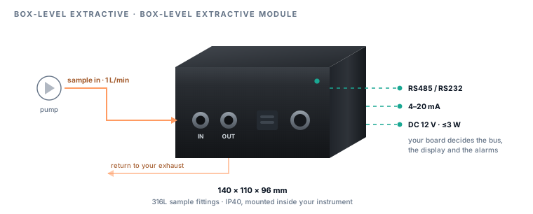
- For extractive systems: take-off, line length and bore, material, filter, pump, flow, regulator, heating, liquid handling and exhaust.
- For direct systems: fitting, insertion clearance, local velocity profile, orientation, isolation and cleaning access.
- Required total response from a process change to the host output—not only the optical module response.
- Whether the reported result is wet basis, dry basis or converted to another reference condition.
Primary and official sources
Sources were checked for the specific claims used here. A cited source does not endorse Specval or establish product performance.
- NIST: tunable-diode-laser absorption measurement paper — Beer–Lambert treatment and the benefit of avoiding sample extraction in an in-situ arrangement.
- US EPA Method 320 text — system response-time and complete measurement-system concepts.
- US EPA OTM-52 text — sample-line material, analyte preservation and moisture-conditioning considerations.
- NISTIR 7052 — facility treatment of gas-sampling delay and analyser response.
Technical review date: 30 July 2026.