Designing Safe Setpoints
If your shutdown is at 22 %vol, the control system must account for the uncertainty band. We provide the data you need to engineer responsible alarm setpoints, hysteresis, and confirmation times.

Zero Delay. Zero Sampling Costs.
Stop relying on slow, high-maintenance extractive systems. By measuring directly inside your high-concentration gas-drainage pipeline, this module delivers the instantaneous CH₄ data your safety and control systems demand—while slashing your total cost of ownership.
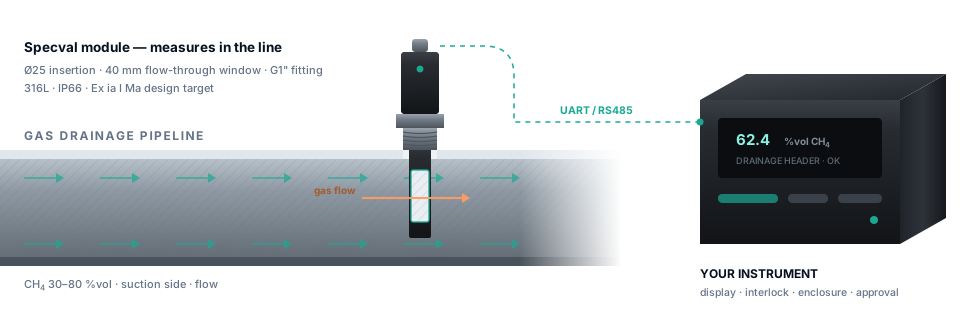
The module measures in the line. The host instrument retains display, alarm, interlock logic, enclosure, field wiring and final system approval.
The Financial Case for Direct Insertion
Traditional measurement relies on extracting gas, filtering it, and pumping it to an analyser. That means buying pumps, heated lines, and filters—and then paying someone to maintain them. Our module bypasses all of that. It inserts directly through a standard G1 inch fitting, placing the optical window exactly where the gas is.
This isn't just about saving money on hardware; it's about operational safety. When a control threshold is breached, a 30-second delay in a sampling line can be catastrophic. Direct insertion gives your control system real-time data. We build the module tough enough to handle the moisture, dust, and pressure variations right at the source, so you get reliable data without the constant maintenance headache.
Smart Mechanical Design
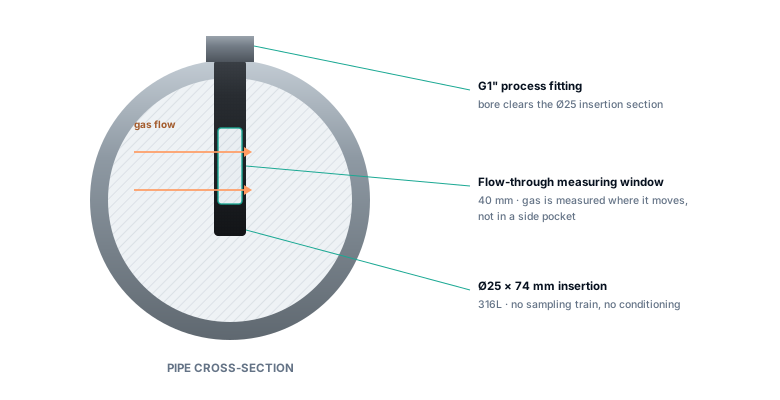
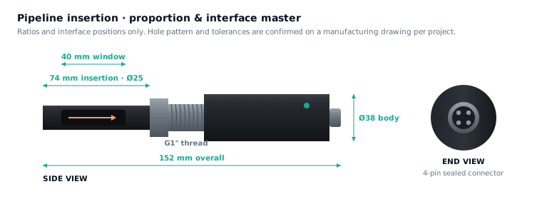
We designed this module to be as unobtrusive as possible while surviving harsh pipeline conditions. The robust 316L stainless steel insertion section (Ø25 × 74 mm) easily passes through a standard G1 inch bore, placing the critical 40 mm optical window directly in the gas flow.
The compact external body (Ø38 × 62 mm) remains safely outside the pipe, housing the electronics and providing a secure connection point. We don't guess on mechanical integrity—every project receives controlled drawings, material certificates, and pressure test documentation to guarantee safety and compliance.
Engineered to fit your specific pipeline geometry
Performance Benchmarks
These specifications represent our rigorous engineering standards. We validate these benchmarks against your specific process conditions to ensure flawless performance in the field.
| Parameter | Target value | Boundary / note |
|---|---|---|
| Target gas | CH₄, single component | Background composition and interferents require project review. |
| Full range | 0–100 %vol | State the normal working band and decision threshold separately. |
| Accuracy, low segment | 0–1.00 %vol: ±0.05 %vol | Target; transition point uses the low-segment value. |
| Accuracy, high segment | 1.00–100 %vol: ±3.5% of reading | Target under defined test conditions; not a system uncertainty budget. |
| Resolution | 0.01 %vol low segment; 0.1 %vol high segment | Resolution must not be interpreted as accuracy. |
| Response | T90 ≤5 s | Target to be reported as gas arrival + window exchange + algorithm window under a defined test. |
| Process pressure | 20–200 kPa absolute | Target operating envelope. |
| Pressure compensation | 20–200 kPa absolute | Target validity band; separate from mechanical survival. |
| Working temperature | −10 to +55 °C | Target; temperature-rate and condensation conditions still matter. |
| Supply | DC 5 V ±10% | Target module input. |
| Power | ≤0.50 W at 25 °C; ≤0.65 W at maximum temperature | Target; highest-temperature consumption is stated because thermal control load changes. |
| Communication | UART 3.3 V standard; RS485 optional | Protocol map and isolation are configured with the host. |
| Process interface | G1 inch thread with hex | Sealing form, pressure class and installation method require confirmation. |
| Insertion section | Ø25 × 74 mm; 40 mm measurement window | 316L target material. |
| External body | Ø38 × 62 mm; approximately 152 mm overall | Anodised aluminium body, matte black target. |
| Ingress protection | IP66 external section | Design target; final assembly and connector determine tested protection. |
| Explosion protection | Ex ia I Ma design objective | Not a certificate. Complete Ui, Ii, Pi, Ci and Li values and system association must be verified before an approval claim. |
| Calibration interval | Target ≥6 months | Must be established by stability evidence and the site’s mandatory calibration rules. |
The Truth About Pressure
Many suppliers boast about high pressure ratings, but they are talking about the mechanical housing, not the optical measurement. In TDLAS, pressure changes the physical shape of the gas absorption lines. If the algorithm doesn't compensate for the exact absolute pressure, your reading will be wrong—even if the sensor housing is perfectly fine.
That is why we strictly separate mechanical survival limits from our pressure-compensation validity band. We engineer the compensation algorithm specifically for the absolute pressure variations in your pipeline, ensuring your data remains accurate under real dynamic conditions.
Read the pressure-envelope method →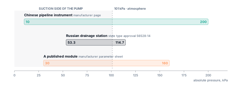
Clear Integration Boundaries
Our module has one job: deliver an ultra-reliable concentration reading and diagnostic status to your control system. We don't force you to buy proprietary displays or redundant controllers. Your host system retains full control over alarms, interlock logic, and user interfaces.
When it comes to safety approvals, we don't make vague promises. For hazardous areas, we provide the exact intrinsic-safety parameters (Ui, Ii, Pi, Ci, Li) your engineers need to perform a compliant associated-apparatus calculation with your chosen barriers and cables.
Review the handover package →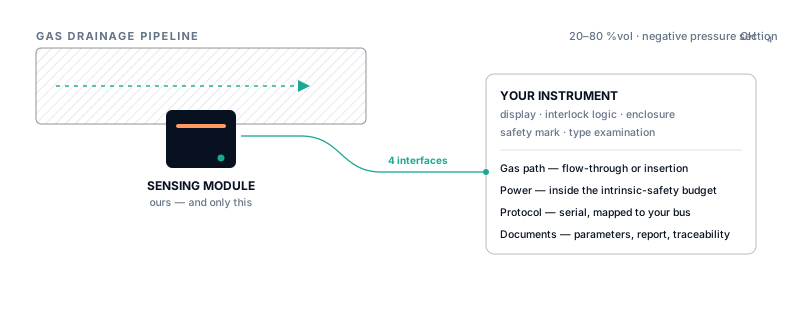
Actionable Accuracy
A relative accuracy spec on a datasheet is useless when you need to program a hard shutdown threshold. We help you convert our performance targets into an absolute uncertainty band exactly where your critical decision is made.
If your shutdown is at 22 %vol, the control system must account for the uncertainty band. We provide the data you need to engineer responsible alarm setpoints, hysteresis, and confirmation times.
True system accuracy must also account for calibration drift, pressure variations, and sampling dynamics. We help you build a complete, realistic uncertainty budget for your specific jurisdiction.
Proven Applications
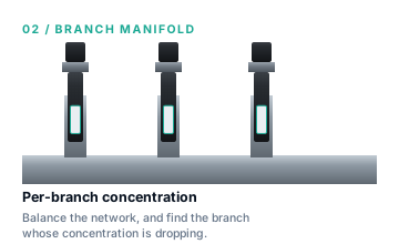
Branch comparison and dilution location.
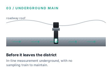
Mixed gas, restricted access and field interfaces.
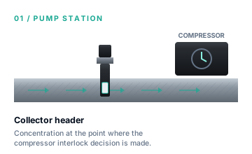
Pressure transients and decision thresholds.
Receiving-process acceptance and protection.
Honest Engineering
If your pipeline cannot accommodate a sealed, maintainable G1 inch fitting in a location with representative flow, you need an extractive system instead.
If your pressure, temperature, or contamination levels far exceed our stated engineering envelopes, forcing this module to fit will only lead to failure.
This module is a component. If you expect it to magically provide complete system-level hazardous area certification without proper barrier calculations, we will decline the project.
Adjacent decisions
Take the Next Step
Share your process conditions—such as absolute pressure, CH₄ range, and environmental factors—and our engineering team will provide a tailored assessment, technical recommendations, and a clear path to deployment.