
 CH₄ppm or %vol configurations
The Heart of Your Analyser
Box-level Extractive TDLAS Gas Measurement Module
Don't settle for legacy sensors that drift and degrade. Upgrade your gas analyser with a high-performance TDLAS core. This compact module integrates directly into your instrument, delivering drift-free, precise concentration data for CH₄, CO₂, CO, and NH₃.
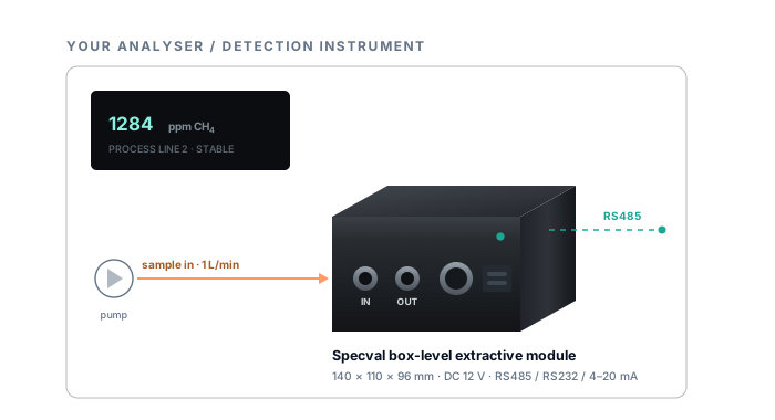
The module performs optical measurement. The host instrument owns sample delivery, user interface, alarms, enclosure and final product approval.
Target GasesCH₄ · CO₂ · CO · NH₃Configured for your specific gas and range.
Optimal Flow Rate1 L/minEngineered for stable, accurate measurement.
Compact Integration0 to +45 °CDesigned for seamless in-instrument installation.
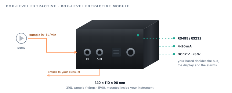
Low Power ConsumptionDC 12 V · ≤3 WEfficient steady-state operation.
Architected for OEMs and Integrators
We Handle the Optics. You Own the System.
Building a TDLAS spectrometer from scratch is expensive and time-consuming. We provide the proven optical core, allowing you to focus on what you do best: sample conditioning, user interface, and system-level approvals. Your conditioned sample enters the IN port, and our module returns a clean, reliable concentration signal.
But we don't just throw a box over the wall. We collaborate with your engineering team to ensure the entire sample path—pumps, filters, and moisture traps—is optimised for the specific gas. For reactive gases like NH₃, we provide critical guidance on wetted materials and flow rates to prevent the gas from disappearing before it ever reaches the sensor.
Partners in performance. A great sensor fails if the sample conditioning is wrong. We share our application expertise to help you build a complete analyser that performs flawlessly in the field.
Multi-Gas Capability
Configured for Your Specific Gas and Application
Choose from four standard gas directions. Each configuration is precisely optimised for your target gas, concentration range, and background matrix, ensuring maximum accuracy and reliability.
CH₄ppm or %vol configurations CO₂ppm or %vol configurations
 COppm configurations
 NH₃sampling material is critical
Other gases are project-adaptation topics, not standard catalogue variants. Different wavelengths may require different lasers, detectors, optical materials, background checks and gas-handling choices.
Designed for Real-World Enclosures
Compact Footprint. Zero Integration Headaches.
Space inside an analyser is always at a premium. We engineered this module to pack maximum optical performance into a tight 140 × 110 × 96 mm footprint. With standard dual stainless sample ports and a robust circular connector, physical integration is straightforward and secure.
We designed the electrical profile to be just as friendly: a standard DC 12V supply drawing less than 3W steady-state. Because this is a box-level component (IP40), we work directly with your team to ensure your final enclosure handles the EMC, grounding, and environmental protection required for your target market.
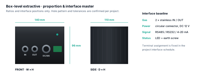
Platform target specification
Shared envelope before the gas-specific configuration
| Parameter | Target value | Boundary / note |
|---|---|---|
| Standard gases | CH₄, CO₂, CO, NH₃ | One configured gas/range direction; others require project adaptation. |
| Housing | 140 × 110 × 96 mm, matte black metal | Target proportion; released drawing governs. |
| Supply | DC 12 V | Host regulation, protection and connector are configured. |
| Power | Steady-state ≤3 W | Target after warm-up; start-up profile to be verified. |
| Outputs | RS232, RS485, 4–20 mA | Configured combination; protocol and scaling require confirmation. |
| Sampling | 2 × stainless IN / OUT ports | External pump and conditioning path required. |
| Nominal flow | 1 L/min | Reference test condition; flow tolerance is gas/configuration specific. |
| Response | T90 ≤30 s at 1 L/min | Module target; total analyser response includes sample transport. |
| Temperature | 0 to +45 °C | Target module environment inside host instrument. |
| Protection | IP40 | Target for inside-instrument use. |
| Explosion protection | Not intrinsically safe | Do not place directly in a mine hazardous area as a standalone field device. |
Transparent Performance
No Inflated Claims. Just Verifiable Accuracy.
We don't use best-case laboratory numbers to sell modules for dirty industrial processes. Our accuracy targets are clearly segmented and tied to explicit test conditions (e.g., 1 L/min, 25 °C, N₂ background). If your process deviates, we tell you exactly how the performance will change.
| Gas | Configured range | Low segment | High segment |
|---|---|---|---|
| CH₄ | 0–5000 ppm | 0–500 ppm: ±10 ppm | 500–5000 ppm: ±2% of reading |
| CH₄ | 0–100 %vol | 0–1.00 %vol: ±0.05 %vol | 1.00–100 %vol: ±3% of reading |
| CO₂ | 0–5000 ppm | 0–500 ppm: ±10 ppm | 500–5000 ppm: ±2% of reading |
| CO₂ | 0–100 %vol | 0–1.00 %vol: ±0.05 %vol | 1.00–100 %vol: ±3% of reading |
| CO | 0–1000 ppm | 0–100 ppm: ±3 ppm | 100–1000 ppm: ±2.5% of reading |
| CO | 0–5000 ppm | 0–500 ppm: ±10 ppm | 500–5000 ppm: ±2.5% of reading |
| NH₃ | 0–100 ppm | 0–10 ppm: ±0.5 ppm | 10–100 ppm: ±3% of reading |
| NH₃ | 0–1000 ppm | 0–100 ppm: ±3 ppm | 100–1000 ppm: ±3% of reading |
These are targets, not one universal platform accuracy claim. Detection limit, background interference, wetted material and exact range are locked in the project configuration. At segment boundaries, the wider stated tolerance governs unless a project specification says otherwise.
The Reality of Response Time
Stop Blaming the Sensor for Transport Delays
Our module reacts in seconds (T90 ≤30s), but that number is meaningless if it takes two minutes for the gas to travel down your sampling line. True system response time must account for line volume, pump flow rate, and the dead volume of every filter and water trap in the path.
first estimate: ttransport = Vline / Q
Use consistent volume and flow units. The estimate does not replace a step-response test of the complete sample system.
Build the sampling boundary →
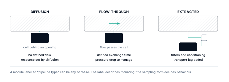
Fast-Track Your Integration
Key Information for a Rapid, Accurate Configuration
Gas and background
Target species, configured range, normal band, balance gas, water, known interferents and any reactive or corrosive components.
Sample path
Take-off location, line length and bore, tubing material, pump, flow, pressure, filters, moisture handling, heating and exhaust.
Host interface
Available space, DC supply, signal type, protocol, warm-up, diagnostics, enclosure environment and document set.
When to Walk Away from Extractive Measurement
If the gas is too reactive to survive the sampling line, if the required transport time is too slow for your safety interlock, or if you need a standalone, intrinsically safe field device—stop here. We will help you evaluate our direct-insertion pipeline module instead.
Adjacent decisions
Continue with the conditions next to this one
Upgrade Your Analyser Today
Get a Tailored Configuration Recommendation
Share your target gas, measurement range, sample path details, and host instrument specifications. Our engineers will design the optimal module configuration for your application and provide a clear path to deployment.