
Direct answer
Hand over controlled interfaces, evidence status and limitations—not only a datasheet.
The receiving team needs a product specification, dimensional and connection drawings, gas-path limits, electrical and protocol definitions, test evidence, environmental limits, diagnostic behaviour, approval status, installation requirements and change control.
Every important value should be labelled as a target, bench result, customer acceptance result or certified value. The package must also state which functions remain with the host instrument and complete system.
1. Integration decisions need controlled information
A marketing page can help an engineer identify a product direction. It cannot define the physical and contractual interface. The host designer needs information that can be reviewed, versioned and traced to evidence. Without that package, assumptions migrate into CAD, software, approval files and test plans without anyone owning them.
The documentation boundary should follow the real interfaces: gas path, mechanical installation, power, signal/protocol, environmental limits, diagnostics, performance evidence and approval status. A box-level module and a pipeline insertion module need different packages because their gas-path and installation responsibilities differ.
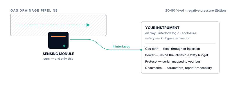
2. Minimum handover package by interface
| Interface | Controlled information | Receiving use |
|---|---|---|
| Product identity | Part/configuration code, revision, intended gas and range | Prevents test data or drawings being applied to another variant |
| Mechanical | Outline, mounting, insertion, fitting, tolerances, materials, seals and connector orientation | CAD integration, strength/sealing review and service access |
| Gas path | Pressure, flow, wetted materials, filtration/conditioning, leak and exhaust requirements | Process and sampling design |
| Electrical | Voltage/current/power, polarity, start-up, grounding, protection and connector pinout | Power budget and protection design |
| Protocol | Physical layer, framing, register/command map, units, scaling, status and timing | Host software and communication supervision |
| Performance | Range, segmented accuracy, response, test conditions, calibration and diagnostics | Acceptance criteria and system uncertainty review |
| Environment | Temperature, pressure, humidity, vibration, ingress and contamination limits | Enclosure, installation and maintenance plan |
| Approval | Certificate or design-objective status, scope, schedules and special conditions | Compliance assessment without overextending the claim |
| Change control | Revision history, notification classes and compatibility statement | Controls re-test and host-product impact |
3. Put an evidence state beside every consequential claim
A target can be useful early in design if it is clearly labelled. The problem occurs when a target appears next to a tested value without distinction, or when a test under one condition is presented as a general product capability.
Target
A design value or intended envelope. It requires an owner, verification method and planned completion point.
Bench result
A measured result tied to specimen, setup, gas, flow, pressure, temperature, procedure and report revision.
Customer or certified result
An acceptance or approval outcome tied to the receiving system or certificate scope. It must not be generalised beyond that scope.
4. Explosion-protection documents have strict scope
An intrinsic-safety design objective is not a certificate. A complete association review may require entity parameters Ui, Ii, Pi, Ci and Li; barrier or associated-apparatus parameters; cable capacitance and inductance; connector and separation controls; schedules; special conditions; and the final system drawing.
IECEx Operational Document 011-2 explains the “U” suffix used for Ex component certificates and the principle that a component cannot be used independently as equipment. The ATEX Directive 2014/34/EU establishes manufacturer conformity-assessment and technical-documentation obligations for the EU scope.
For the current pipeline insertion development, Ex ia I Ma is a design objective. The complete intrinsic-safety parameter set is a required engineering output; values that have not been established must remain unknown rather than being invented to complete a table.

5. Use an ownership matrix before document production
| Deliverable | Module supplier | Host integrator | System / site owner |
|---|---|---|---|
| Module specification and interface drawing | Owns and releases | Reviews and accepts | Receives as needed |
| Host power, enclosure and wiring | Provides limits | Owns design | Reviews installation |
| Gas take-off or process fitting | Provides module boundary | Coordinates | Owns process suitability and authorisation |
| Alarm and interlock cause-and-effect | Provides output/fault behaviour | Implements logic | Owns approved operating action |
| System approval and field acceptance | Supports within scope | Compiles host evidence | Owns site acceptance unless agreed otherwise |
6. Define which changes trigger review or re-test
Laser type, optical path, cell material, wetted surfaces, pressure sensor, algorithm, calibration model, connector, power stage, firmware protocol and explosion-protection-relevant components can all affect evidence. A revision number alone does not tell the customer whether a change is form/fit/function compatible.
A useful change notice states what changed, why, affected serial/configuration range, interface impact, evidence reviewed, re-test performed and required customer action. Critical changes should be agreed before shipment, not discovered during incoming inspection.
7. Common failure modes
Brochure used as the specification
It has no configuration code, tolerances, test conditions, pinout or controlled revision.
Certificate scope overextended
A component, sample or previous configuration is used to imply approval of the complete host system.
Unknown values silently filled
Intrinsic-safety or pressure values are guessed to make an interface table appear complete.
Firmware changes outside change control
Filtering, diagnostics or communication timing changes without updating response or host validation.
Primary and official sources
Sources were checked for the specific claims used here. A cited source does not endorse Specval or establish product performance.
- IECEx standards resources — official standards and certification-system context.
- IECEx OD 011-2 — official operational document addressing Ex components and the “U” certificate suffix.
- Directive 2014/34/EU (ATEX) — official EU legal text for equipment and protective systems intended for potentially explosive atmospheres.
- IECEx guide to drawings and documentation — official guidance supporting controlled certification documentation.
Technical review date: 30 July 2026.