Gas drainage line
The measurement point is inside a gas drainage pipeline. The gas is methane-rich, the installation is Ex-classified, and the process connection is G1″ or can be adapted to it.

Developed by Specvaltech · Gas drainage pipelines
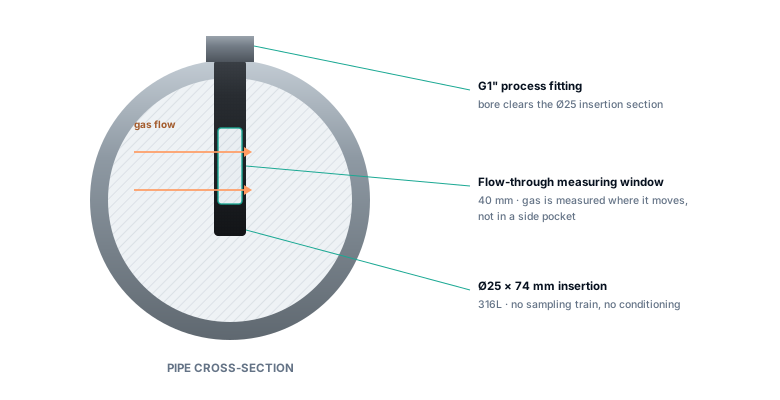
This module measures methane inside a gas drainage pipeline. The insertion section passes through a G1″ process connection and the measurement window sits in the gas flow, so there is no sample line, no pump and no conditioning stage between the pipe and the reading.
In-pipe flow-through
An extractive installation measures gas that has been taken out of the pipe. Between the process and the reading there is a tap, a sample line, usually a filter and a condensate stage, a pump, and a flow control. Each of those elements adds a delay, and each one can change the sample before it is measured.
An in-pipe flow-through installation removes all of them. The measurement happens where the gas already is.
That is not automatically the better choice. It moves the optical window into a wet, dusty, moving stream, and it moves maintenance from a cabinet you can reach to a pipe you may not be able to isolate. What it buys is a reading that describes the pipe rather than describing what arrived at the analyser several seconds ago.

Constraint chain
Most of this specification is a chain of constraints rather than a set of independent choices. The chain is worth showing, because it is what tells you whether a supplier has actually built the thing.
The chain in words
Ø25 insertion section. The process connection is G1″, whose bore is about Ø30. The insertion section has to pass through it, so Ø25 is the working diameter with clearance.
40 mm measurement window. The window sits inside the 74 mm insertion length, leaving material at both ends.
0.65 W at maximum temperature. The intrinsic safety envelope for Ex ia I Ma sets an input power limit of 0.688 W. At 5 V that is 130 mA, giving 0.65 W with about 5 % margin. The high-temperature figure is given separately because thermoelectric cooling draws the most current at the top of the temperature range.
Accuracy given in two segments. A 0–100 %vol range forces a short optical path. A short path limits sensitivity at low concentration. So the low segment is quoted as an absolute value and the high segment as a percentage of reading. A single percentage of full scale across the whole range cannot hold.
T90 at 0.1 m/s and above. The window is 40 mm long, so at 0.1 m/s the gas in it is replaced in 0.4 seconds. Above that velocity the limiting term is the algorithm averaging window, not the flow.
Platform specification
Figures apply at 25 °C, 101.3 kPa absolute, methane in nitrogen balance, after warm-up.
| Parameter | Value |
|---|---|
| Target gas | CH₄, single component |
| Measuring range | 0–100 %vol |
| Accuracy, below 1.00 %vol | ±0.05 %vol |
| Accuracy, 1.00–100 %vol | ±3.5 % of reading |
| Resolution | 0.01 %vol below 1.00 %vol; 0.1 %vol above |
| Response, T90 | ≤5 s at a pipe gas velocity of 0.1 m/s and above |
| Operating pressure | 20–200 kPa absolute |
| Pressure compensation range | 20–200 kPa absolute |
| Operating temperature | −10 to +55 °C |
| Supply | DC 5 V ±10 % |
| Power | ≤0.50 W at 25 °C; ≤0.65 W at maximum operating temperature |
| Communication | UART 3.3 V standard; RS485 optional |
| Gas path | In-pipe flow-through, window in the insertion section |
| Insertion section | Ø25 × 74 mm, 40 mm measurement window |
| Process connection | G1″ thread with hex |
| Body | Ø38 × 62 mm, 152 mm overall length |
| Materials | 316L insertion section; anodised aluminium body |
| Ingress protection | Designed to IP66, exposed section — Design objective |
| Explosion protection | Ex ia I Ma — Design objective, see below |
Two notes that belong with the table.
The accuracy segments meet at 1.00 %vol. At that point the low-segment figure of ±0.05 %vol is the wider of the two and it governs.
Pressure compensation range and mechanical pressure rating are different specifications. The compensation range is the interval over which the reading is corrected. A module can be mechanically safe at a pressure where its reading is no longer corrected.
When this module fits
The measurement point is inside a gas drainage pipeline. The gas is methane-rich, the installation is Ex-classified, and the process connection is G1″ or can be adapted to it.
The working concentration is in the range where drainage gas operates — typically 30–80 %vol. The 0–100 %vol range covers the full envelope including the critical zone near the explosive range.
The installation allows a 74 mm insertion section to enter the pipe through the process connection, with the body remaining outside. Insertion depth and pipe diameter are confirmed before configuration.
Limits
If the pipe diameter does not accommodate a G1″ connection, or if insertion depth is restricted to less than 74 mm, the module cannot be installed as designed. This is a geometry constraint, not a configuration option.
Below 20 kPa absolute the reading is outside the compensation range. Above +55 °C the module is outside its operating temperature. Very low gas velocity (<0.1 m/s) means the reading describes the window, not the line.
Ex ia I Ma is a design objective, not a certificate we hold. If your installation requires a held certificate at the module layer, this is not the right module until that certificate exists. We do not ask you to choose on the basis of a design objective.
Accuracy at an interlock threshold
At a 22 %vol trip point, ±3.5 % of reading gives an error band of ±0.77 %vol. We publish the figure the platform holds rather than the one that would read better. → Run the numbers on your own threshold
Delivery boundary
| We deliver | We do not deliver |
|---|---|
| Optical engine: laser, in-pipe flow-through cell, detector | Your equipment’s national safety certificate |
| Drive and demodulation electronics | System-level interlock and alarm logic |
| Calibration data and algorithm firmware | On-site installation and field calibration service |
| Self-diagnostic output and communication protocol stack | Filing and management of your type testing |
| Bench test report with the test conditions stated | |
| Component traceability and integration documentation | |
| The documentation inputs your certification route requires |
What we need from you
Target gas and measuring range, and your interlock or alarm threshold if there is one · Operating pressure range, stated as absolute or gauge · Gas temperature, and whether condensation occurs at the measurement point · Background composition · Pipe diameter, available process connection, and any limit on insertion depth · Pipe gas velocity range · Electrical, communication and host system interface · Your jurisdiction and the certification route your equipment follows · Where responsibility for interlock logic and alarm handling sits.
Items you can answer move into qualification. Items you cannot are recorded as unknown with a way to resolve them — a sample test, a document, or a question to your certification body. We do not close an unknown with a customisation promise.
→ Certification routes for the same measurement point, compared across jurisdictions
Take the Next Step
What comes back is one of four things: which structure may fit, what is already confirmed, what still has to be verified, and whether the next step is a technical discussion, a sample test, a quotation, or stopping. If a fit does not exist, that answer usually arrives faster.